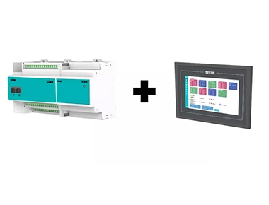
In recent years, with the rapid development of highway construction in the central and western regions of China, the number of tunnel projects has continued to increase, and the mileage of tunnel construction has become longer. People have paid more attention and importance to tunnel power supply technology and power monitoring technology. According to Article 11.5.1 of JTG D70/2-2014 "Design Specification for Highway Tunnels", highway tunnels with central control and management facilities should be equipped with an electric power monitoring system.

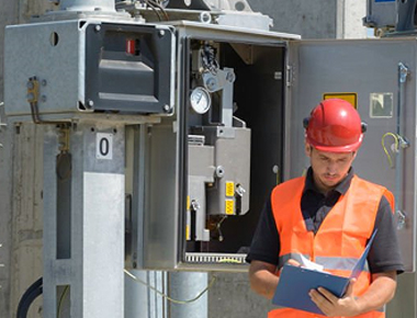
In the facilities of highway routes, tunnels are accident prone points and weak links in operation and management. In general, tunnels are located in remote mountainous areas, far from the central control and management center, with scattered electrical equipment and multiple power supply points, making operation, management, and maintenance very difficult.
The use of an electric power monitoring system can achieve unmanned operation of tunnel substations, improve the efficiency of operation management and equipment maintenance, quickly obtain information on the operation status of various electrical equipment and switches, and timely troubleshoot to reduce fault losses.
Design scheme and functions
Summary
Based on the characteristics of strip distribution and scattered points in tunnel power supply and distribution, we have utilized the advantages of fiber optic networking and integrated advanced technologies in power automation, computer communication networking, and automatic control to design the ELECNOVA-PMS tunnel power monitoring system.
The ELECNOVA-PMS tunnel power monitoring system collects real-time operation status of power supply equipment such as highway and tunnel lighting and ventilation through monitoring equipment set up at sub stations. It focuses on monitoring the status of transformers and key incoming and outgoing circuits, collecting fault action signals, accelerating the response and processing speed of power grid accidents, and shortening the power outage time of faults; Comprehensively collect electricity consumption data to analyze changes in various loads and power consumption costs; The central monitoring station can also remotely control the distribution and corresponding switches and circuits (such as lighting and ventilation circuits).
System structure
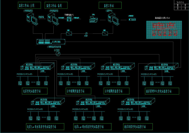
The power monitoring system adopts a hierarchical structure that combines industrial Ethernet with optical fiber as the transmission medium and industrial fieldbus with serial communication as the main transmission medium, divided into three levels:
Level 1: Monitoring Management
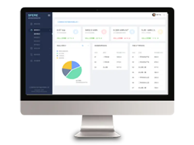
Set up power monitoring workstations in the management center.
The power monitoring workstation mainly completes advanced applications for power monitoring of various substations in the tunnel, as well as functions such as interfaces with other systems.
The main station obtains real-time data information of the power supply and distribution system from the power monitoring systems of each monitoring substation, calls and statistics the load status, load distribution curve, important alarms, accident statistics, working status and other power monitoring data of each substation, monitors and controls the power supply and distribution system as a whole, analyzes the operating status of the power supply and distribution system, and effectively controls and manages the entire monitored power supply and distribution system to ensure that it is in the optimal operating state. The management center will receive real-time effective data from each substation to ensure its grasp of the global operation status of the power supply system and coordinate the operation of various monitoring systems.
The monitoring management team is mainly equipped with the following software and hardware devices:
Power monitoring workstation: Hardware platform for power monitoring operation management;
Power monitoring application software: Power monitoring operation management software platform.
Level 2: Communication intermediate layer
The data transmission between each monitoring substation and the management center is achieved through a high-speed fiber optic communication network, and each monitoring substation uses fiber optic communication channels to transmit data to the power monitoring workstation for data processing.
Power monitoring utilizes the communication interface provided by the tunnel monitoring system to communicate with the management center, transmitting power monitoring data to the power monitoring host of the management center. The tunnel monitoring system generally provides a 100M communication channel at each substation's power monitoring substation, with an interface of RJ45.
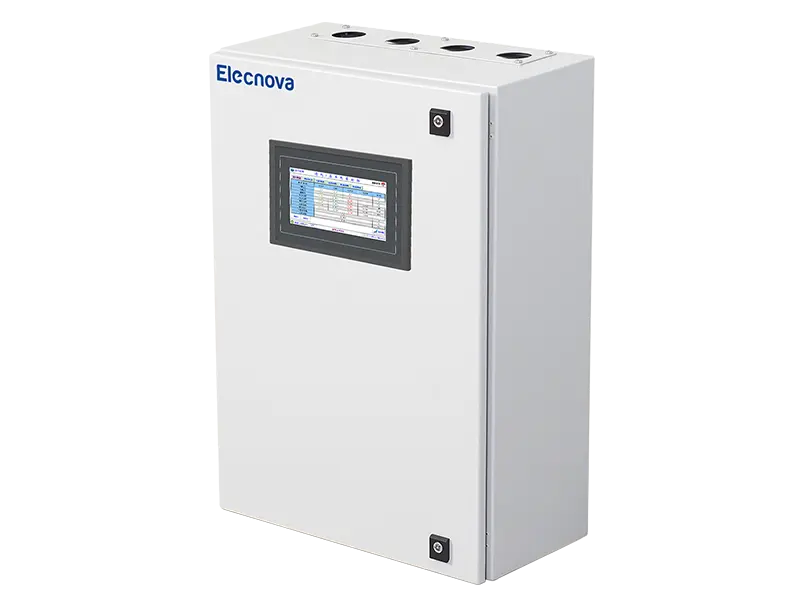
Each monitoring substation is equipped with a communication management machine with an Ethernet interface. The communication management machine is connected to a 100M fiber optic communication channel for uplink, and communicates with the power monitoring workstation in the management center through the 100M fiber optic communication channel; The downlink communication interface of the communication management machine is RS485 interface, which communicates with the intelligent protection and measurement device in the substation, collects data information from the terminal device, performs protocol conversion, data processing, data forwarding, and uploads valid data to the power monitoring workstation.
The communication middle layer is mainly equipped with a communication management machine to achieve functions such as monitoring data management, transmission, forwarding, and protocol conversion.
Third level: Terminal device layer
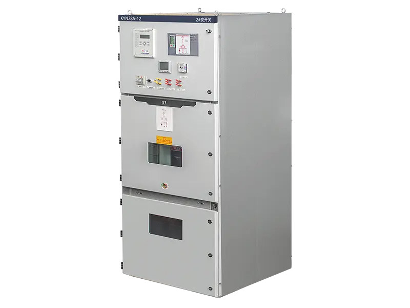
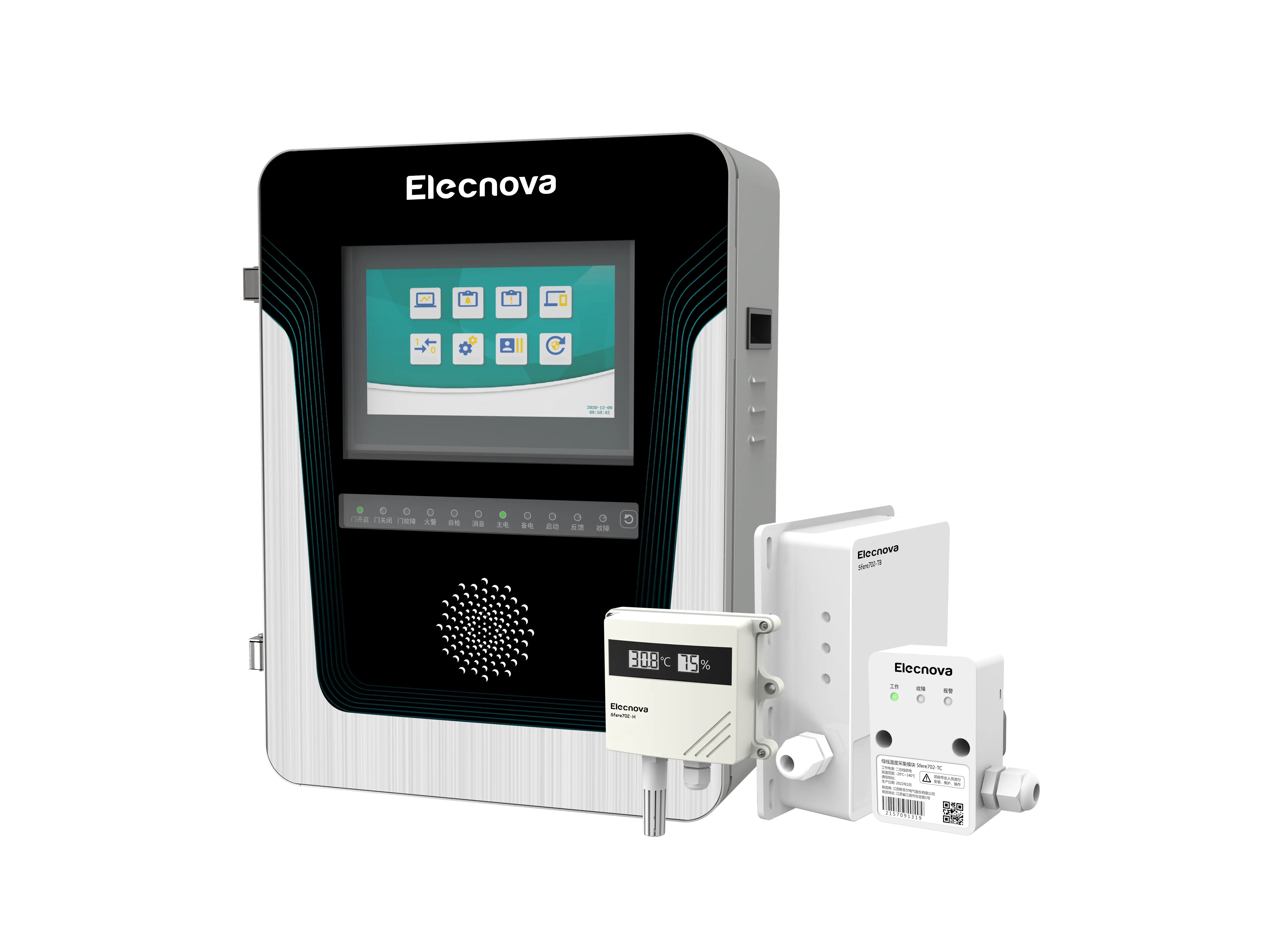
The monitoring of each substation, in principle, refers to a monitoring substation where each substation or equipment is relatively concentrated. The monitoring substation monitors and controls transformers, high and low voltage equipment, etc. inside the substation.
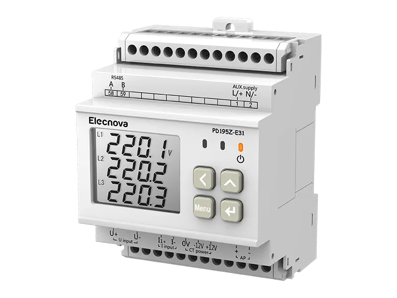
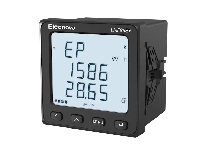
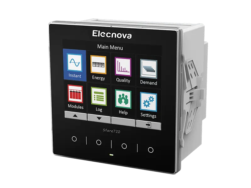
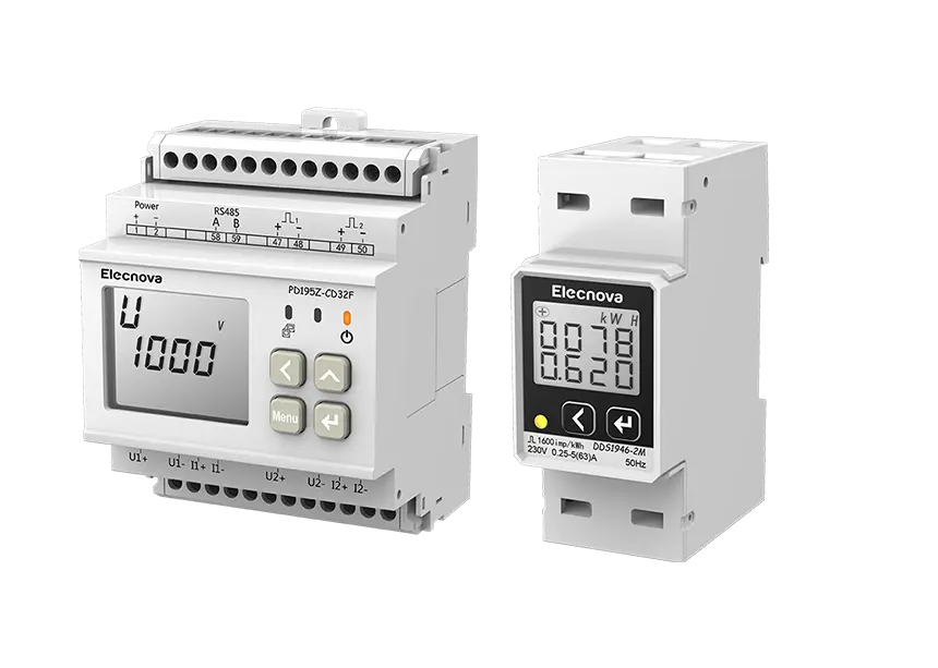
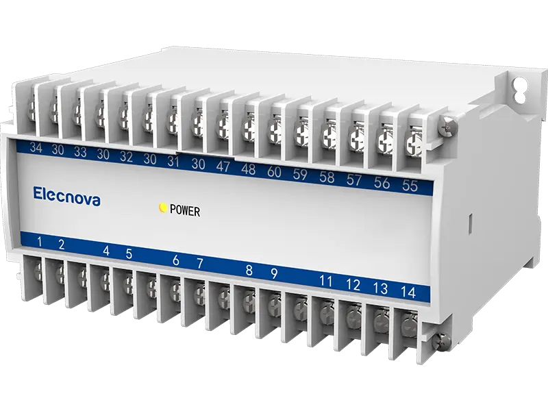
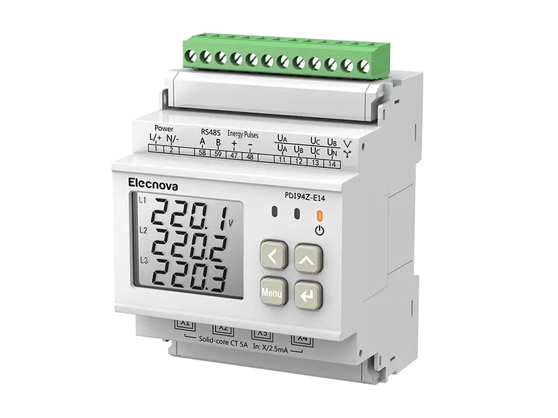
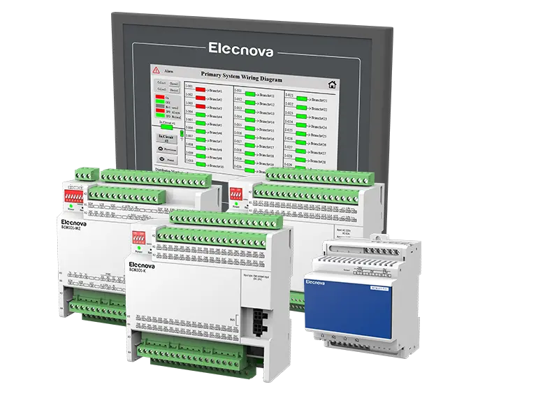
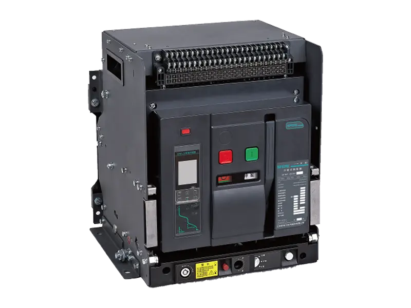
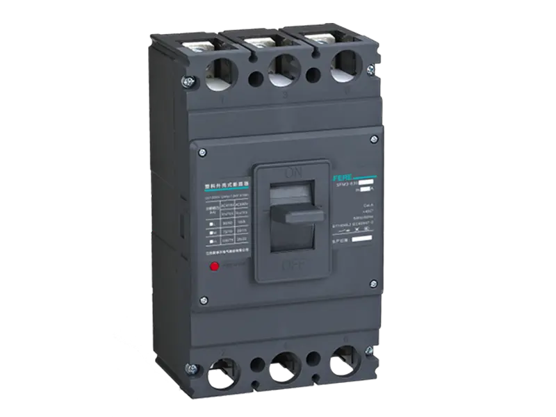
The comprehensive monitoring terminal equipment layer device adopts a modular and modular structure, with an object-oriented (high-voltage incoming and outgoing lines, low-voltage incoming cabinets, reactive compensation cabinets, 0.4kV distribution circuits, transformers and other equipment objects) standard mode configuration for data collection and centralized conversion transmission. It mainly consists of 10kV system microcomputer protection and measurement integrated device, 10kV motor protection and measurement device, 0.4kV system three-phase multifunctional digital measurement and control meter, three-phase multifunctional digital meter, single-phase digital ammeter, low-voltage motor protection and measurement device and other equipment.
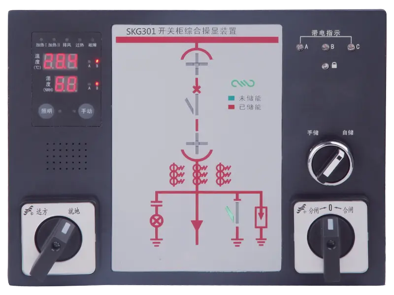
The 10kV microcomputer protection and measurement integrated device completes the relay protection function, data monitoring function (telemetry information), information collection function (remote signaling information), control output (remote control) function, etc. of the 10kV system;
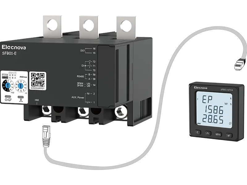
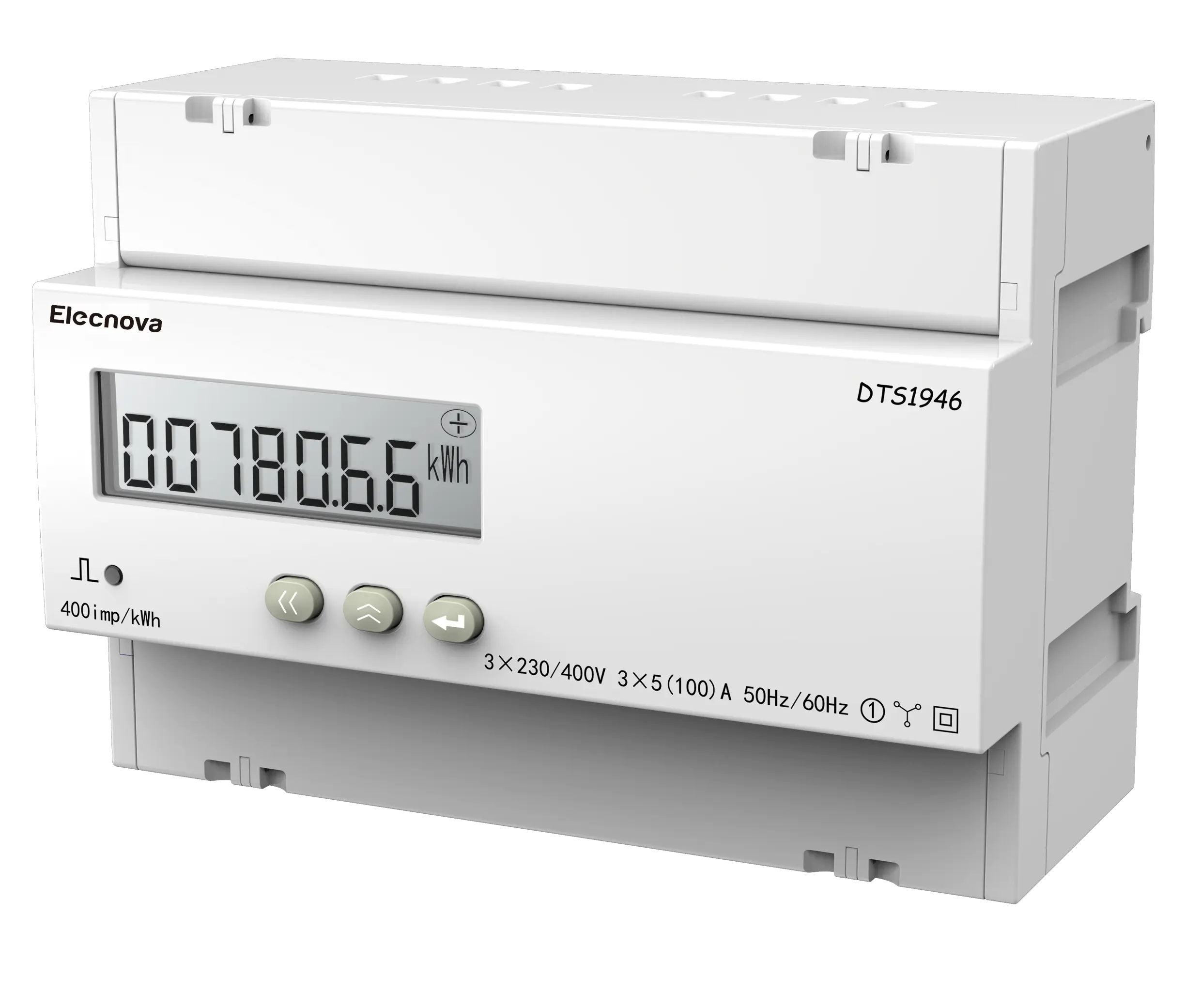
The 0.4kV three-phase multifunctional digital measurement and control meter completes data monitoring functions (telemetry information), circuit breaker status and limit exceeding control and alarm (remote signaling information), circuit breaker opening and closing (remote control) functions, etc;
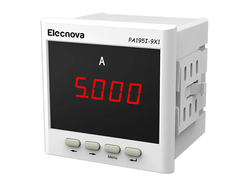
The 0.4kV single-phase digital ammeter completes functions such as single-phase current (telemetry information) and circuit breaker status (remote signaling information);
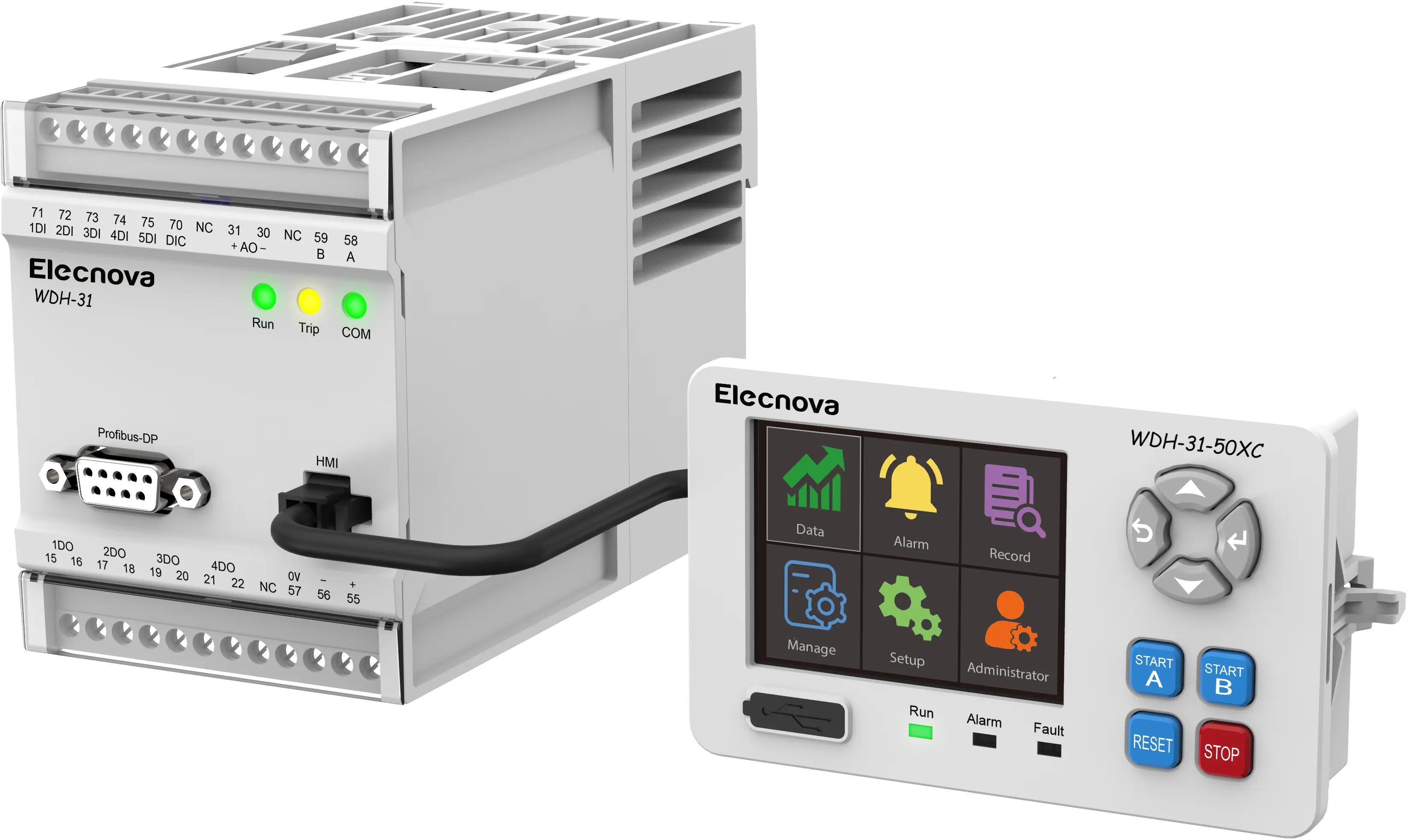
The 0.4kV low-voltage motor protection and measurement device completes the functions of overheating protection, grounding protection, overcurrent protection, phase loss protection, imbalance protection, rotor blockage protection, and monitoring for the fan;
The distribution transformer protection and measurement device completes functions such as temperature monitoring, fan control, and fault alarm for dry-type transformers.
The communication management unit exchanges information and transmits commands with various intelligent microcomputer measurement and control terminal devices through RS232 network communication.
Each intelligent terminal is installed on the panel of power components such as incoming and outgoing switches in the substation, mainly for data collection and control of power equipment, recording information on line short circuits and grounding faults.
System function
Cockpit
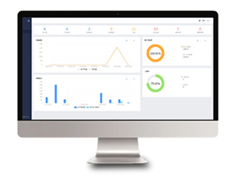
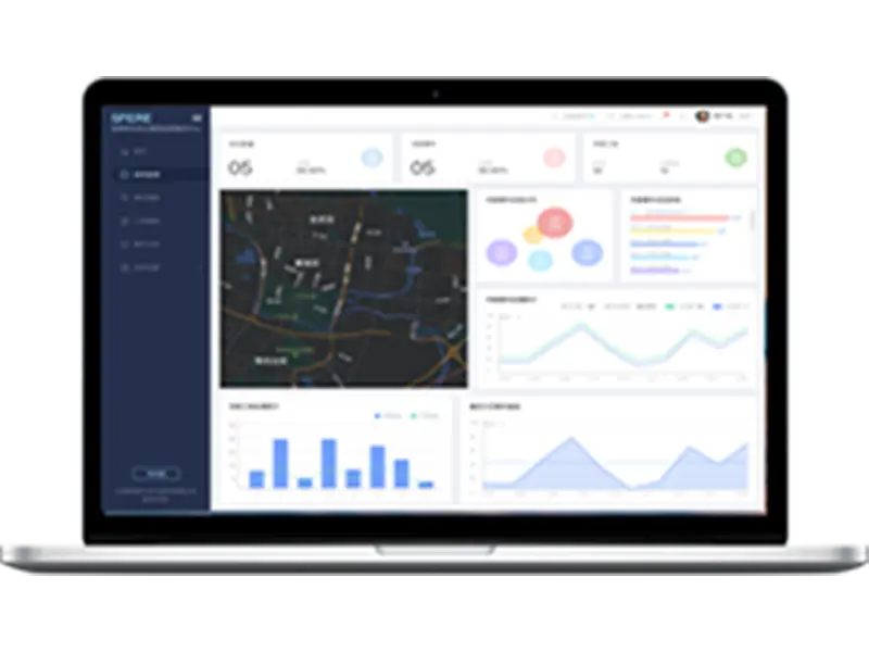
Display the location of the substation managed by the current user on the map, and distinguish the operation status of the substation through different colors (green: normal operation; red: alarm; yellow: fault; gray: offline), allowing users to intuitively and conveniently understand the operation overview of all substations.
Real time monitoring
Real time monitoring is the core functional module of the tunnel power monitoring system. Through this, users can grasp the operational status of the monitored site and circuit at all levels, and build a "shortcut" between users and data.
Site level:
Operation monitoring, system diagram, simulation diagram, environmental monitoring, access control monitoring, video monitoring, topology diagram. Fully grasp the status of the station and achieve unmanned operation of the station building.
Loop level:
Real time acquisition of operating parameters (telemetry) and operating status (remote communication) of terminal monitoring equipment, mastery of circuit electrical operation situation, remote execution of equipment remote control and adjustment commands, and real-time reminders of events.
Operational analysis
The system stores the collected electricity data in history, and operators can query data from any past time period in the form of reports or curves, such as generating electricity daily reports, monthly reports, annual reports, and trend curves of various real-time electricity quantities (such as power, current, etc.) that meet user requirements.
The report system needs to be customized according to user specific requirements, ensuring that the style and data fully meet user printing requirements and habits, and supporting export.
The system can meet the real-time monitoring data analysis needs of users, and can perform extreme value analysis, time period analysis, horizontal comparative analysis, vertical comparative analysis, etc.
Electricity analysis
Users can set alarms for various electrical parameters of each circuit through the computer's interactive interface. For example, they can set the upper limit value of a certain circuit's current. As long as the circuit current exceeds this value, the system will immediately generate an alarm and output it to the computer interface to alert the user (which circuit has triggered an alarm, etc.). At the same time, the system records all alarm records, making it convenient to analyze the capacity and load of each circuit.
Power quality analysis
The system is like a 24-hour personal doctor, conducting all-weather physical examinations on electrical circuits, comprehensively analyzing the source of the disease, issuing diagnostic reports, timely reminding hidden dangers for treatment, and changing from "passive" to "active". The system platform utilizes WEB and APP to push warning information to operation and maintenance management personnel anytime and anywhere, guiding them to carry out electrical hazard management, eliminating potential electrical fire hazards, and achieving scientific management of electrical energy.
Smart operation and maintenance
Smart operation and maintenance management can achieve comprehensive monitoring of all distribution rooms 24/7, providing comprehensive operation and maintenance management, improving operation and maintenance efficiency, and ensuring electricity safety.
Remote monitoring: Realize comprehensive monitoring of the environment and security of the distribution station building, achieve unmanned monitoring, and improve inspection efficiency.
Operation and maintenance management: Perform work order distribution, work order modification, work order verification, work order feedback and other operations on platform events, and record historical work orders for users to query.
Event Management
The main functions of system event management include: current events, historical events, and overall, querying and managing the current and historical events monitored by the system.
File management
Archive management is divided into asset management and lifecycle management.
Asset management: Register and manage information for all connected devices, and add relevant materials such as equipment manuals and operation manuals for easy access by relevant personnel.
Life cycle: Monitor the usage date, effective time, and remaining time of all connected devices to ensure their normal operation without affecting measurement and protection accuracy.
System management
System management includes notification center, user management, role permissions, system logs, account management, and interface settings
Notification Center: Unified management of platform notification information.
User Management: A page for maintaining, creating/deleting users, and resetting passwords for platform users.
Role permissions: A page for maintaining system role permissions, creating/deleting roles, and modifying role permissions.
System log: View user operation records at the system level.
Account Management: A page where users can modify passwords and edit information for their own accounts.







 CN
CN EN
EN
 fr
fr  de
de  es
es  it
it  ru
ru  ar
ar  vi
vi  tr
tr  th
th 

